Sound, Waves And Vibration ~ Part I
 by Itzhak Bentov
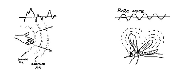
We are constantly surrounded by sound. We even have a highly specialized opening in our heads for making sounds that may be meaningful to other people. We communicate through sound; in fact, it is our major means of communication. When we disturb the air in any way, we create sound. The slightest motion of our bodies disturbs the air around us, and we produce sound. When we raise our hand, we compress the air in its way, and that compressed air front will travel away from us at the speed of sound, which in air is about 740 miles per hour. When we make periodic movements with our hand, the sound becomes a note. By sound we mean here any random acoustical disturbance that may be composed of many different frequencies. A note, on the other hand, is a sound of a single frequency. We call this kind of sound “infrasound,” that is, sound below our level of perception. However, when a fly or a mosquito beats its wings, it does it fast enough, and we sure can hear it. The rapid flapping of its wings produces evenly spaced compressions and rarefications of the air that become audible to us. In short, a fly or a mosquito is producing a sound or a note.
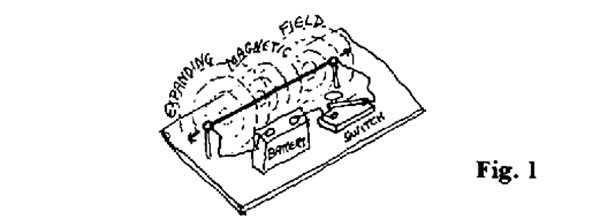
Let us try to make sound in a less obvious way. We shall take a short piece of wire, connect both its ends to a battery through a switch (Fig. 1) and close the switch.
We were told in school that three things happen: (1) that electrical current will run from one side of the battery to the other; (2) that a magnetic field perpendicular to that current will shoot out and expand all the way to infinity at the velocity of light, which is about 186,000 miles per second; and (3) that the wire will heat up slightly. They probably did not tell us: (4) that when the wire heats up, it expands, and by so doing it will clearly force the air out of its way and make a kind of sound; or (5) that as the mass of the wire is accelerated in this way, it will produce gravitational waves since any time a mass is accelerated, it will broadcast gravitational waves, which will again expand to infinity at the velocity of light.
Some will say that the gravitational waves will certainly be almost infinitesimally weak. But that does not worry us as long as they are there. So our action of closing the switch has been broadcast, theoretically at least, to the outer limits of the atmosphere around the earth due to the movement of the air and was broadcast all the way to the end of the universe by the expansion of the magnetic field around the wire and by the gravitational wave due to the wire’s acceleration.
The purpose of this example is to show how, in principle, even our smallest, most insignificant actions will be broadcast far and wide and thus influence something or someone — whether that something or someone is aware of it or not.
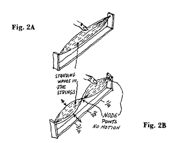
We should look now at other effects of sound. If we stretch a string on a frame (Fig. 2A), then pluck the string in the middle of its length, we shall see the outline of the string in the extreme positions of its movement; it forms two symmetrical arcs, as shown. If we pluck the string at the one-quarter mark of its length, we shall see a shape as in Figure 2B.
These are standing waves. We get such waves only when plucking the string at distances that will divide the string into integral numbers. In Figure 2A, the frame length corresponds to half a wave, while in Figure 2B the frame accommodates a full wavelength. In Figure 2B, the string has a point in the middle at which the string is at rest and two more points at which it is attached to the frame. Such points of rest are called nodes. All the other points of the string are vibrating up and down. When the nodes along the string appear stationary and fixed while the rest of the string is vibrating, we call such a behavior a “standing wave.”
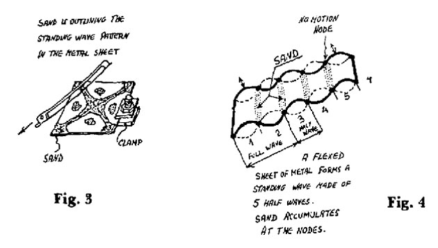
Suppose we now take a thin sheet of metal (Fig. 3), clamp it at one edge so that it stays in a horizontal position, spread some dry sand evenly over this sheet, then take a violin bow and draw it over one of the free edges of the sheet until it emits a note. Very soon we shall see that the sand grains are collecting on the sheet in a symmetrical pattern. As we apply the bow at different points along the edge of the metal, we shall get different and quite beautiful patterns on the sheet.
The reason for this aggregation of sand grains is that we are setting up the so-called standing waves in the metal. These standing waves in the metal sheet are a two-dimensional version of the standing wave in the string. These standing waves have active areas that vibrate up and down and other areas or nodes that are quiescent. The sand grains will move away from the vibrating areas and accumulate in the quiescent areas. The sand grains like to be left in peace, and they will go to the quiet, low-energy places. This pattern in sand actually outlines for us the pattern of standing waves in the metal sheet. The standing waves automatically divide the length and width of the plate into an integral number of half wave-lengths (Fig. 4). It is only then that a standing wave can be sustained. This is so by definition. Standing waves cannot exist unless they divide their medium into an integral number of half waves. A standing wave having a fractional wavelength cannot be sustained.
We can also put it another way: The dimensions of the plate are the factors that govern what is the size or wavelength of the standing wave that can be sustained in the plate. When a structure is in resonance (which means that it vibrates at a frequency that is natural to it and is most easily sustained by it), it implies the presence of a standing wave. Let us see if we can visualize this kind of behavior in three dimensions. We could take a transparent box (Fig. 5), fill it with a fluid, and disperse particles in it with the same specific gravity as the fluid so that they stay dispersed in the fluid and do not sink to the bottom. Then, by vibrating the walls of this box from all six sides in a synchronous manner, we could cause these particles to aggregate in a symmetrical three-dimensional pattern. This pattern will look just like a highly enlarged crystal if we assume that the aggregated lumps are analogous to the atoms in a crystal. We have again produced a standing wave pattern in this box, which is a three-dimensional analog of the standing wave in the string and the metal plate. At the same time we have produced a three-dimensional object analogous to a basic building block in Nature and a highly ordered crystal — and we have done this simply by applying sound to an amorphous, disorganized suspension of particles.
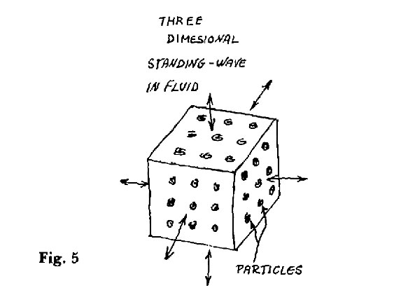
In the box we have set up an interference pattern of standing waves (which we will soon explain) that governs the position of the particles. In short, by using sound, we have introduced order where previously there was none. It may occur to us that a crystalline structure may be seen as representing sound interacting in a volume. Is it possible that the orderly pattern of atoms in matter is the result of the interaction of some kind of “sound waves” in matter?
Superposed Sounds
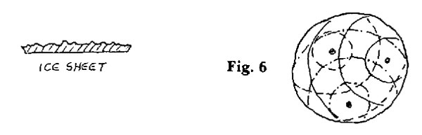
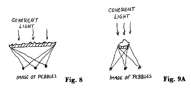
Now let us go one step beyond and see whether “sound” can also be used for storing information or knowledge. A shallow round pan and three pebbles are all we need for this experiment. Fill the pan with water. Now drop in the three pebbles simultaneously, as shown in Figure 6, and watch the ripples spread in the pan. Each pebble is the source of waves spreading evenly across the pan. (Let us neglect the wavelets reflected back from the walls of the pan.) These waves cross each other and create quite a complex pattern of wavelets on the surface of the water. They look pretty chaotic to us. There is, however, an order in this apparent chaos. All that has happened is that the wave produced by each individual pebble expanded and reached the edge of the pan. In so doing, the waves have crossed and interacted with each other on the way to the edges of the pan. This interaction* created a complex pattern that is called an interference pattern. If we carefully analyze this pattern, however, we can trace back each wavelet to its source, the pebble. Let us now quick-freeze the surface of the water in the pan and lift out the resulting rippled sheet of ice. We are holding in our hands a record of the interference pattern of waves, or we may even call it a hologram.**
*Superposition is included in the broader term of “interaction.”
**A hologram is usually a flat photographic film on which information is recorded about the shape of the object in the form of a wave-front interference pattern. When this film is illuminated with the same light under which the information was originally recorded, the wave front is reconstructed, and the image appears in space as a three-dimensional object, identical in “shape” to the original object. See Kock, Winston E., Lasers and Holography. New York: Doubleday-Anchor, 1969; London: Heinemann Education. 1972.
Interference Patterns And Beat Frequencies
In order to clarify what an interference pattern is, we have to learn two additional properties of sound in its different forms: (1) constructive and destructive interference; and (2) beat frequencies.
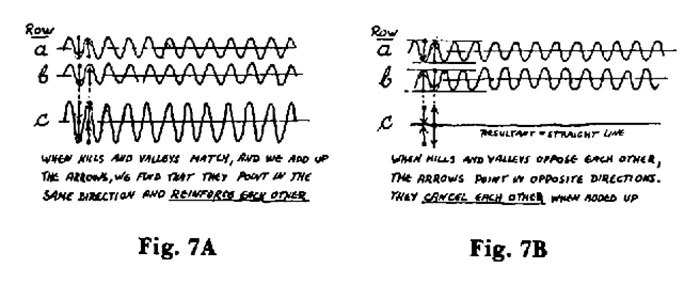
Let us take the first one. In Figure 7A, you will see what happens when two wave patterns of identical frequency and amplitude, or wavelength, meet. Let’s try to superimpose them on each other. In Figure 7A, we see that the hills and valleys of the frequencies in Rows a and b match each other. If we superimpose them by measuring their heights or amplitudes from their respective baselines, then we find that hill matches hill, and valley matches valley. And when added up, they produce a wave form twice the height of the original wave forms, as shown in Row c. This is known as constructive interference because it builds up the amplitude.
If we now look at Figure 7B, we find that hills match valleys, and valleys match hills. And if we add them up, we shall find that they cancel each other out, as the flat line in Row c indicates. This is known as destructive interference. This is what is happening in our pan of water. If we look at the ripples in the ice sheet, we shall find that where hill meets hill, we end up with a hill double the original wave height, and where hill meets valley, we find just a flat spot. This is the nature of an interference pattern. However, many forms of interference patterns are possible. We may have them in a single dimension — as when we vibrate a string — or in two dimensions — as in our flat pan; or in three dimensions — as in our box in Figure 5.
Beat Frequencies
Now that we know what an interference pattern is, it will be relatively easy to understand a beat frequency. In Figure 7C we see a frequency in Row a — let’s say it is 50 cycles per second — and a frequency in Row b — which let’s say is 60 cycles per second. If we add them up as we did before, we shall discover an interesting phenomenon. Row c shows the result of adding the two frequencies. What we see is a pearl-shaped wave form superimposed on top of our a and b wave forms. The reason for this becomes obvious if we examine Figure 7C carefully. Starting from the left, we see that in Row c the amplitude (wave height) is low where the hills and valleys oppose each other and high where both wave forms coincide or reinforce each other, which results in constructive interference. The wave patterns are said then to be in phase, to use a technical term.
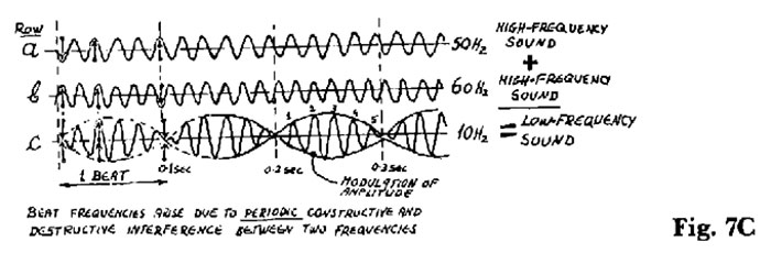
Now, as we move to the right, we notice that the a and b waves gradually go out of phase, and the hills start facing the valleys, thus opposing each other, which means that a destructive interference is occurring. This destructive interference reaches its maximum in every fifth cycle, forming a narrow “waist” in the amplitude or “volume” of the sound at those points.
The pearly pattern in Row c will therefore be a “modulation” of the basic sound, which has a fixed amplitude. Modulation means a change that is being caused in an otherwise smooth or even behavior. In our case, it means an increase and a decrease of the amplitude or “volume” of the 60 and 50 cycle, per second sound. This modulation will occur 10 times per second with minima occurring every six cycles.
This 10 Hz.* modulation is called a beat frequency and is the difference between the a and b frequencies, or 60 Hz. minus 50 Hz. = 10 Hz. Were we to make a a 10 cycle per second sound and b a 12 cycle per second sound, we would then have a 12 minus 10 = 2 cycle per second beat frequency superimposed on these two basic frequencies. The knowledge of these two properties of “sound” will be important as we proceed. Note that the difference between the two fast frequencies produces a third frequency that is much slower than the first two. This, then, is a beautiful device for converting high frequencies to low ones.
*One cycle per second is expressed in technical language as 1 hertz, abbreviated 1 Hz.
Suppose now that due to a momentary gap in attention or plain clumsiness, this ice sheet slips out of our hands, drops on the floor, and breaks. We sadly collect the pieces, but before throwing them all out, we hold up one of them and illuminate it the same way as we did the large sheet. To our great surprise, we find the three pebbles again projected in midair (Fig. 9A). But how come?
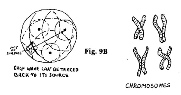
You may remember that the information about the whereabouts of each pebble was carried by the waves moving to the edge of the pan. We know if we drop just a single pebble into the pan, it would be very easy for us to locate it. We would simply seek out the center of the concentric wave rings or wave fronts. We know also that the waves from each pebble crossed the face of the whole pan; naturally, they must have interacted with each other across the whole surface of the pan on every square centimeter of its surface. We can show it like this: The arcs created by each pebble are crossing a small piece of the surface, and each arc can be traced back to its origin (Fig. 9B). This is the basic principle of the hologram. However, I would not recommend that you actually try to perform the experiment just described. It will not work in practice for certain complicated technical reasons, which we shall bypass. But it is perfectly useful for the purpose of explaining the workings of the most exciting information-storage device, the hologram. It is nature’s way of storing information. There is already evidence that our brains store information in a holographic form. This kind of storage device is the most compact known in Nature. An example of this is the genetic code carried in our chromosomes. Each cell in our bodies carries all the information required to make an additional copy of our bodies.
Our success in storing information in the system just described depends, naturally, on the predictable and orderly behavior of the waves in the pan. They must be consistent both in velocity and in distance between the waves or wavelengths. This is what makes them reliable as carriers of information; otherwise, all we would get is a hodgepodge of waves. Here is where coherency comes in.
Coherency
It would be good at this point to describe the way a real hologram is made so that you become familiar with this important concept.
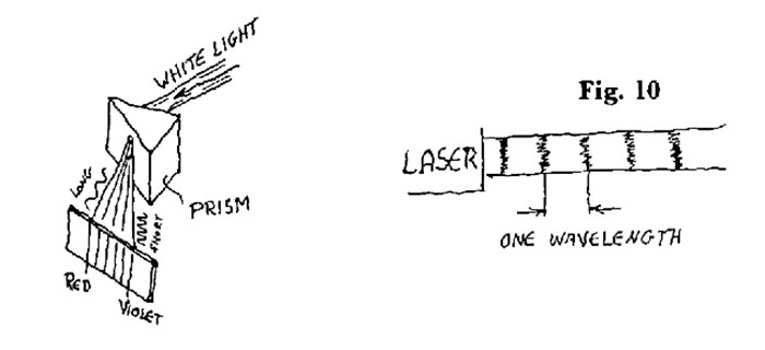
By coherency we mean an order of a certain kind. In this case, we shall talk about coherent light, without which a good hologram cannot be made. The most popular source of coherent light is a laser. The first important aspect of laser light is that it produces light of a single frequency. We all know that our sun sends us light that can be broken down by a prism into a spectrum containing all the colors of the rainbow. A laser produces light of just a single color from that rainbow, which we call “monochromatic light.” In addition, the light emitted by the laser is coherent, or goes in step. By that we mean that all the light coming out of the source is moving forward in even, flat fronts (Fig. 10). This makes it possible for the laser light to stay in a narrow beam over very large distances.
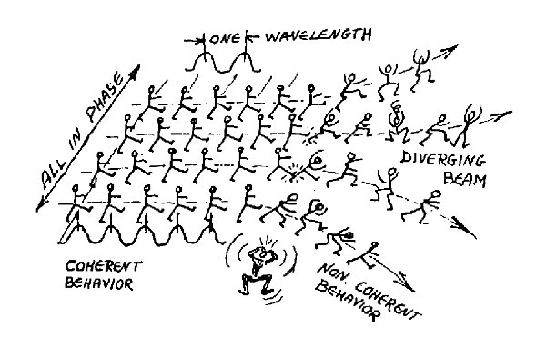
There is a better way to describe coherency. Suppose we have a parade and a company of soldiers marching in military fashion down a main street. They are moving along, ten abreast, very carefully aligned in each row. The distances between the rows are fixed, which is analogous to the even distances between the crests of light waves. That they are carefully aligned abreast, none of them sticking out of the line, is analogous to the light being in phase or “in step.” In short, the row of soldiers is analogous to the light emitted by the laser beam. Suppose now that a slip-up occurs, and one of the soldiers, not watching his fellows, shifts out of his row, moves forward, and steps on the heel of the fellow in front of him. The latter panics, thinking that he is lagging behind, and he jumps forward and bumps into the fellow ahead of him. Now this starts a general panic in which soldiers bumping into each other disrupt the nice even width of the moving column. The neat column diverges, broadens, then opens up completely in great disorder in spite of the fact that their commander is blowing his whistle, tearing at his hair, and using strong language to get his men back into line. What we have learned from this disastrous parade is that a beam of light can stay in a narrow beam similar to a laser’s beam only as long as it is coherent. When coherency is lost, the beam will tend to expand rapidly just as will the beam of a regular flashlight.
Excerpt from Stalking The Wild Pendulum
See Part II here.

Related posts:


Posted in Other Topics, Science For The New Agewith 1 comment.